Monday, June 1, 2015

Retrofitting an analog power supply with a digital meter


Intro

I bought an old an HP 6294A DC power supply from the Dayton Ham fest back in 2013.  The guy I bought it from promised that it worked fine, and I took it home for pretty cheap.  The supply did work, but the dual voltage/current meter on the front didn't.  It was surprisingly hard to find a replacement meter, and it was going to be very expensive.  Instead, I continued to use the supply (with an attached multimeter). I recently came across a cheap digital display, and I decided to swap it in.  

The meter

The meter.  DROK 100V, 10A, internal shunt.  ~$12 from amazon.  Probably could have found it cheaper elsewhere.

DROK® Small Digital Amperemeter Voltmeter Multimeter 0.28" DC 100V 10A Car Voltage Ampere Meter 2in1 with Built-in Shunt Red/Blue 2-color LED Display 12V 24V Motorcycle Battery Monitoror
DROK meter


DROK meter with wire colors explained.  The two small wires (black and red) power the meter.  The meter power can be any DC supply from 4.5 to 30V.  The three larger wires (red, yellow, black) are the inputs for the meter.  

DROK wiring schematic.  The red wire is the voltage sense and attaches the high voltage side of the load.  The yellow wire is the negative side of the load.  The black wire connects to the HP Power supply common.  

The Supply

As it turns out, the HP 6294A DC power supply is a purely analog DC power supply.  This means that there are NO convenient 5V, 12V, etc. rails to tap into for the meter.  Therefore, I had to use a wall wart (see below) to power the meter.

Safety

Before I did ANYTHING, I unplugged the supply from the wall and gave the capacitors (there was one really big one) time to discharge.   

The Install


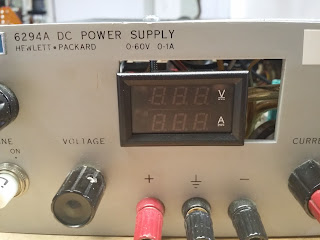
I pulled out the old meter, and soldered in the new meter using the wiring diagram I showed before.  The wires that connected to the old meter were useless for the new meter.  Therefore, I enclosed the exposed wire ends with electrical tape so they wouldn't accidentally touch something.  

A closer look.  

I wired the wall wart with a stiff piece of copper wire to the AC input of the supply.  I twisted the wire with pliers until taunt and then soldered everything together.  The wall wart was quite secure.  

I tapped a hole and added a screw through the top plate of the supply to clamp the meter in place. 

The Final Product

Both the volt meter and current meter work!
The downside to this build is that the meter stays lit even when the supply is turned off.  This is because the wall wart is attached to the AC input of the supply.  Oh well.  There are certainly worse problems to have.