Tuesday, December 9, 2014

EAGLE PCD layout of quarter bridge strain gauge

Intro

I don't use EAGLE PCB often enough and subsequently forget how to use it between uses.  To that end, I'm writing this quick example/tutorial to remind myself how to use EAGLE.  Maybe you can make use of this too.  Also maybe one day I'll be using it enough to become a pro.  Until then...

The circuit I'm modeling is a 3-wire, quarter bridge strain gauge, Figure 1, attached to an INA125 instrumentation amplifier, Figure 2.  The three wire circuit shown in Figure 1 minimizes any offset resistance due to resistance in the wires.  The INA125 is used because it has both a clean 10V reference voltage to power the quarter-bridge and a single resistor to control the amplifier's gain.  

Figure 1.  3-wire quarter bridge circuit.  E is the excitation, and e_o is the voltage measurement.  

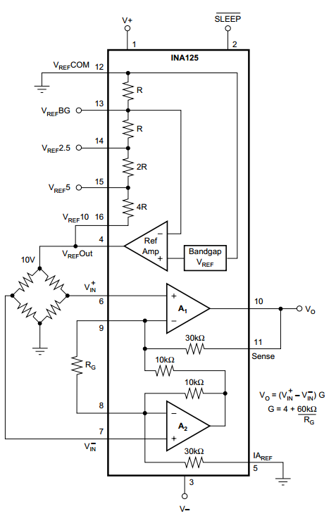
Figure 2.  INA125 instrumentation amplifier.  Notice the wheatstone bridge on the left side.   

Setting up EAGLE

First, make sure you have the latest version of EAGLE installed.

Next, you need to download some helpful EAGLE libraries.  (The lack of native easy-to-use libraries is one of my biggest criticisms of EAGLE.)  Element14, Adafruit, and Sparkfun all provide additional libraries that are a little simpler to navigate.  Read this link on how to install your libraries.

I also strongly recommend copying all useful libraries to a separate folder so you can find them easier in the future.  For example, I've created a folder called 'JohnsUsefulLibraries', and inside, I have a library for throughhole resistors, throughhole ICs, throughhole trimmers, etc.  To do this, File->New->Library and save it accordingly.  Next, right click on the new library and click open.  Then find the schematic (which should be linked to all of the related parts) in other libraries, right click on it, and click Copy to Library.  Save the new library.

EAGLE Step-by-step procedure to create parts

Schematic

Start with the schematic.
  1. Look through your library and place all parts that you'll need.  
  2. Give each part a Name and Value.  
  3. Move/rotate/mirror/etc each part until you have it where you want it.  
  4. Click "Net" and connect all parts that need to be connected.
  5. Under the supply library, you'll find ground and power symbols.  These are great because they reduce the clutter on your schematic while still being "connected".  Use these and make sure all relevant power or ground symbols have the same name (e.g. all ground symbols should be Named GND) to keep them connected.  
  6. Once done, click "Generate/switch to board"
Figure 3 shows my schematic.  I'm using 3x1 headers as place holders for my standoff connectors (which I couldn't find the part for).    

Figure 3.  EAGLE PCB layout of quarter-bridge strain gauge circuit.  

Board

  1. Turn Grid on.  
  2. Move components about where you want them.
  3. Click ratsnet to redraw the "unconnected" lines.
  4. Ground plane
    1. Resize board to something reasonable.  
    2. Change to "Top" layer
    3. Draw polygon around the outside of the board.  Red line should become dotted when connected. 
    4. Change polygon name to GND (name of ground connection).   
    5. Click ratsnet button.
  5. Cleanup silkscreen (optional)
    1. Smash names.
    2. Move and delete desired values.  
  6. Set autorouting values.  
    1. Edit -> Net classes.  
    2. Change traces to maybe 12mil, drill to maybe 20mil, and clearance to maybe 10mil.
  7. Autorouting
    1. Click autorouter.
    2. Continue.
    3. Optionally, place each route manually.  

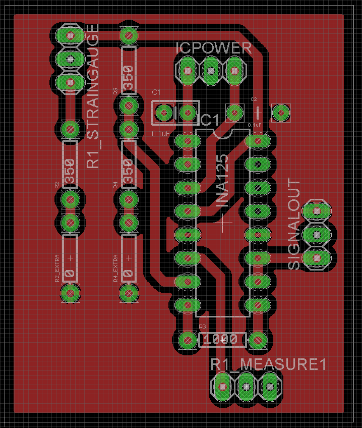
Figure 4.  EAGLE PCB board layout.  The 0 ohm resistors are there in case I need a second resistor to better balance the bridge circuit.  If I don't need it, I'll just jump it.  


Wrapup

Depending on how you want to have your board developed, there will be additional steps.  I'm presently using a Vinyl cutter and Ferric Chloride to make mine.  For details on this process, see my tutorial on Vinyl Etching PCB Boards.

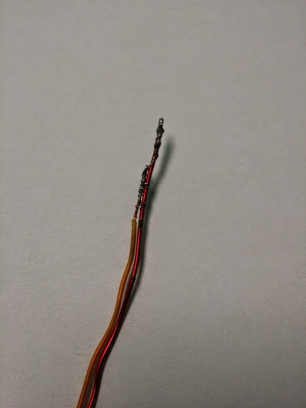
My final product is shown below.


Resources

INA125 - Instrumentation amplifier
EAGLE tutorials created by Jeremy Blum


Wednesday, November 5, 2014

Pointwise - Converting 2D Plot3d grid files to 2D Plot2d

Introduction
I was trying to use Pointwise to generate Plot2d grids, and I discovered that Pointwise appears to be only capable of generating Plot3d grids.  I couldn't find a solution inside of Pointwise so I wrote the Matlab script below to address it.

A quick explanation on the difference between 2D-Plot3d and 2D-Plot2D grids.  When generating a 2D grid in Pointwise, the program outputs a z-coordinate for each point (which is always 0).  Here's an example of the difference between the 2D-Plot3d and 2D-Plot2d grid file:

2D-Plot3d
2
30 30 1
59 30 1
...xdata(block 1)...
...ydata(block 1)...
...zdata(block 1) = 0...
...xdata(block 2)...
...ydata(block 2)...
...zdata(block 2) = 0...

2D-Plot2d
2
30 30
59 30
...xdata(block 1)...
...ydata(block 1)...
...xdata(block 2)...
...ydata(block 2)...

Why does this matter?  

First, Vulcan doesn't care.  When importing the grid file into vulcanig, the user can specify if it is a Plot3D or Plot2D file, and Vulcan will take care of it.

However, TecPlot DOES care.  Because the output of vulcan is in a true 2D format, TecPlot cannot plot the solution against the 2D-Plot3D grid.  It needs the 2D-Plot2D grid.  


The code

The following code is written in MATLAB

clc; close all; clear all;

%% input
inputFile=['C:\Users\John\Documents\PointwiseExample','\','expansionChamber.x'];
outputFile='grid.x';

%% read in 2D(x=m,y=n,z=1) data
A0 = importdata(inputFile);  %raw data
A=A0;  %raw data to be trucated

% number of blocks in data
numBlocks=A(1);

% grab matrix sizes from the header
for i = 1:numBlocks
    m(i)=A(2+(i-1)*3);
    n(i)=A(3+(i-1)*3);
end

% throw away header info from A
A=A(2+numBlocks*3:end);

% grab x and y data from A and ignore z
for i = 1:numBlocks
    N=m(i)*n(i);
    x{i}=A(1:N);
    A=A(N+1:end);
    y{i}=A(1:N);
    A=A(N+1:end);
    A=A(N+1:end); %delete z
end


%% plot data
figure; hold on
colors=['brkg'];
for i = 1:numBlocks
    plot(x{i},y{i},[colors(i),'+'])
end


%% write 2D(x=m,y=n) data (with the single z value stripped out)
fileID = fopen(outputFile,'w');

% write number of blocks
fprintf(fileID,[num2str(numBlocks) '\r\n']);

% write matrix sizes for each block
for i = 1:numBlocks
    fprintf(fileID,[num2str(m(i)), '\t', num2str(n(i)), '\r\n']);
end

% write x and y data for each block
for i = 1:numBlocks
    p=x{i};
    for k=1:2
        if k==1
            p=x{i};
        else
            p=y{i};
        end
        
        while(length(p)>=4)
    %         fprintf(fileID,[num2str(p(1)), '\t', num2str(p(2)), '\t', num2str(p(3)), '\t',num2str(p(4)), '\r\n']);
            fprintf(fileID,'%1.15e\t%1.15e\t%1.15e\t%1.15e\r\n',p(1),p(2),p(3),p(4));
            p=p(5:end);
        end
        if p~=0
            for j=1:length(p)
                fprintf(fileID,'%1.15e\t', p(j));
            end
            fprintf(fileID,'\r\n');
        end
    
    end
end


Sunday, November 2, 2014

DIY rocket igniters

Introduction

For a side project at work, we needed to develop a consistent method of igniting our hybrid rocket motors.  After a bit of poking around, I decided to pursue igniters, and I'm sharing some of the results of my findings here.

Scroll down to the bottom if you want to see the video first.

Warning - DANGER!

Hopefully everyone is aware that playing with gunpowder and rocket igniters is dangerous.  I recommend only doing this is you are comfortable handling explosives and you have someone supervising (regardless of your age).  Also, please wear safety glasses!

How to make

I used this website to help me get started, and I recommend reading through if you are at all interested in making your own igniters.

Step one is the prepare the wires.  Start with two wires of similar lengths.  I'm using a small 24 gauge wire (orange) and a larger magnet wire (red) as shown in Figure 1. The magnet wire is very stiff and should hopefully shoot out the rocket nozzle without clogging it after it ignites.  Take the wires, strip the ends, and place them in parallel.  Also, make sure that the magnet wire sticks out a little past the smaller wire (Figure 1) and that the exposed portions of the two wires CANNOT make contact.  Take a very small diameter wire (I used Nichrome but copper will work too), wrap one end around the exposed magnet wire and the other end around both the magnet wire (which is protected with insulation) and the exposed 24 gauge wire.  Solder both ends.  Checks the resistance (with an ohm-meter) of the wire, and it should be under 1 ohm (but not zero).  The previous website I mentioned also does describes this process.

Figure 1.  The prepared ingiter wire prior to dipping in the pyrogen.  

The next step is to mix 3 ping pong balls (must be made of nitrocellulose or NC) with 4+ ounces of acetone in a sealed container (I used a mason jar).  I then waited 24 hours for the ping pong balls to dissolve in the acetone (if it doesn't dissolve, you bought knock-off ping pong balls that are not made of NC) .  When it was done, all of the solid had gone away, and I was left with a liquid a little more viscous than water.   This step makes your NC lacquer which acts as a combustible binding agent for your later additives (gunpowder, etc).

Figure 2.  Mix 3 ping pong balls (front-right) in 4+ ounces of acetone (back-right) in a sealed container (left).  Wait 24 hours.

Step three is to grind your gunpowder into a fine powder.  I'm using American Pioneer Powder - FFFG granulated black powder.  Add the granulated powder to a mortar and pestle and grind until the powder stops getting smaller.

Figure 3.  Grind your blackpowder into a fine powder.  The gunpowder shown here has not been ground enough.  

Next step is to mix the lacquer with your gunpowder.  I poured about 5-10 milliliters into a plastic mixing cup and slowly added ground black powder until the mixture was thick but still a fluid paste.  This forms the pyrogen. Practice will help you quickly determine the right viscosity.  Also, either add a little magnesium to the pyrogen now (and mix) or sprinkle it on the final product while it's drying (in the next step).

Figure 4.  Mix the lacquer (right) with finely ground black powder (middle) in a mixing cup (front right).  Either add (and mix)  a little magnesium powder now or wait for the next step.

Next, dip your prepared igniter wire into the pyrogen, extract, and allow to dry.  Move quickly because the acetone quickly evaporates from the pyrogen, and the mixture in the cup has already started to harden.  The viscosity of the pyrogen will determine how thick of a coating of a coating will form on the wire, and this is important because your rocket's throat diameter may limit the size of your igniter.  If you haven't already mixed the magnesium powder into the pyrogen, sprinkle some onto the drying igniter.  The following figure shows my final product.

Figure 5.  Final igniter product.  

The magnesium in the previous steps burns at a hotter temperature than the blackpowder alone, and it also throws out large sparks.  In theory, these two facts should provide a higher chance to light your rocket motor.

Firing

The following video shows the igniter firing.  Notice that sparks (the burning magnesium) that jumps from the ingiter while it's burning.  The sparks are also shown in Figure 6 below.


Figure 6.  The magnesium powder in the igniter throws out very hot sparks during combustion and should improve the chance of a successful ignition.  


Wednesday, October 8, 2014

VULCAN-CFD tutorial 1 - Installation

Intro

The purpose of this tutorial is to document the steps for setting up VULCAN-CFD on Ubuntu or Ubuntu inside of Windows Virtual Box.  I personally have only a limited about of Linux and CFD experience, and there is practically no support for Vulcan online.  I'm posting here both for my record and for those who come after me.  Good luck.

For the following Virtual Box install, I'm using Ubuntu 12.04, Vulcan 6.3.0, openmpi 1.8.3, Virtualbox 4.3, and Windows 7.

For the following Ubuntu stand-alone install, I'm using I'm using Ubuntu 12.04, Vulcan 6.3.0, openmpi 1.8.4.

If you're wanting to install Vulcan in Windows, this tutorial does a fantastic job walking you through the process of setting up Ubuntu in Virtual Box.  Make sure you download the correct Ubuntu build (32/64 bit and version number).  To my knowledge, Ubuntu 12 is the last version that works with Vulcan.

If you're wishing to install Vulcan on a stand-alone Ubuntu install, worry not.  These directions will work for you as well.  Make sure you're using Ubuntu 12 instead of 14.  I don't believe Vulcan-CFD is compatible with Ubuntu 14 yet.

Initial Ubuntu Setup

The video below will walk you through the process.

Below here, I list all of the steps shown above in the video.
  • Update apt-get
sudo apt-get update
  • Install the following packages.  Make sure you're using the latest builds particularly with tcl8.5 and tk8.5.  
sudo apt-get install gfortran build-essential m4 flex g++ tcsh tcl8.5 tk8.5
  • Download and install openmpi, a program that allows for parallel processing.  Go to the Open-Mpi website (http://www.open-mpi.org/), and download the latest build.  Extract the files, and navigate and change the directory in terminal to the openmpi directory (e.g. cd ~/openmpi-1.8.4/ or whatever your directory is).  Execute the following two commands to install:
./configure F77=gfortran FC=gfortran
sudo make all install
  • Create the folder ~/Vulcan and extract your current version into that folder.  The full path to this directory should be ~Vulcan/Ver_6.3.0 or whatever the latest build is.  
  • Create/open the .tcshrc file (a customization file for tcsh) with the following command, copy and paste the following lines in (with any updates to the directories if necessary, and save.  
sudo gedit ~/.tcshrc

setenv LD_LIBRARY_PATH /usr/local/lib
source ~/Vulcan/Ver_6.3.0/Scripts/vulcan_config
source ~/Vulcan/Ver_6.3.0/Scripts/vulcan_config_gui
setenv TCLGRIDGPATH /
setenv TCLTECPLPATH /
setenv TCLPOSTPPATH /
set history=1000
  • Edit the vulcan config file:  ~/Vulcan/Ver_6.3.0/Scripts/vulcan_config, uncomment the following lines, and save.  This link has more details on this step.
Step 1:  setenv PLATf Linux_AMD_GFC_64
Step 2:  setenv VULCAN_comp_prec double_prec
Step 3:  setenv VULCAN_run_mode parallel_openmpi
Step 4:  setenv VULCAN_rmt_protocol ssh
Step 5:  (skip)
Step 6:  setenv VULCAN_METIS disable (this may be wrong)
Step 7:  (skip)
Step 8:   set mpi_cmnd = 'mpiexec -machinefile $vulcan_mpi_hst -n $num_cpus $vulcan_cmnd'
  • Edit the vulcan config gui file:  ~/Vulcan/Ver_6.3.0/Scripts/vulcan_config_gui, uncomment the following lines, and save.  This file sets up some of the vulcan front end and gui programs, but I've found these to be very buggy.  I also don't understand all of the inputs below.  I do the best I can, but I have no doubt that these aren't 100% correct.  I do, however, believe that whatever you put in here doesn't have a big influence on Vulcan's performance.  
Step 1:  setenv WHICHWISH /usr/bin/wish
Step 2:  (skip)
Step 3:  (skip)
Step 4:  (skip)
Step 5:  setenv TCLBROWSER /usr/bin/firefox
Step 6:  setenv TCLEDITOR  /usr/bin/gedit
Step 7:  (see below)
Step 7 here confuses me, and I'm not sure what to put in for each of these inputs.  I do my best, but I know I'm not doing this right.  
setenv VULCAN_sc_nodes_1 1  #(no. of sub-cluster nodes)
setenv VULCAN_sc_cores_1 4  #(no. of processing cores per node)
  • Install Vulcan.  Type the following commands:
tcsh
source ~/.tcshrc
cd  ~/Vulcan/Ver_6.3.0/Scripts/
./install_vulcan new

  • Finally, run a few examples cases to make sure it works.  

Thanks to:

Jonathan French for providing my first introduction to Vulcan as well and help with installation on several occassions.  
Josh Batterson for helping with installation.
Robert Baurle for maintaining Vulcan-CFD and by giving me permission to post this material on the web)

Wednesday, July 2, 2014

DIY 1000 deg C Temperature Controlled Oven

Intro

I needed a high-temperature, temperature-controlled oven for various experiments, and the design below is the product.  The finished internal dimensions (including the soft brick and insulation) are 12.25" x 22.125" x 7.5".  

For full disclosure, the oven has only reached 940 deg C, but with more settling time and better insulation, it would easily achieve 1000+.

Oven

Oven parts list:
K-23 Soft Insulating Fire Bricks (10??)
Standard (hard) Fire Bricks  (40??)
Ceramic insulation (~4 ft)
Steel L-stock
Nichrome heating elements (6)
Chimney Cement (several tubs)
Steel plate
L brackets (2)
Threaded rod
Misc. nuts and bolts

The oven is designed such that every part exposed to heat is rated for very high temperatures (the lowest is somewhere around 2000 dec C) in case I decided to put in a second set of heating elements (which would require a second 240 V line) and push the oven hotter.

I started by assembling the base out of steel L-stock and welding the frame together.  I next stacked fire brick around the bottom and sides to make the oven.  I used chimney cement to seal the seams after placing the bricks.  I didn't cement the entire length of the bricks because I didn't need the structural support and only wanted to stop air flow. It also will make disassembling the oven in the future more of a possibility.  Next, I machined grooves in the soft fire brick using a router mounted to a CNC, and placed the firebrick in the oven as shown in the pictures.  I made extra grooves in case I ever want to add additional heating elements.  The soft brick is so soft that hand tools (powered or manual) can do the job as well [1].  I also drilled holes through the hard fire brick to serve as feed troughs for the nichrome.  I stretched the nichrome heating elements so that they were long enough to run two lengths of the chamber, placed them in the soft fire brick, placed and passed the leads through the hard fire brick.  I then used the remaining chimney cement to seal these holes.  Next, I placed the insulation on the bottom surface and the two exposed sides.

The lid is composed of a steel sheet (I don't remember where I bought it) with insulation bolted to the bottom.  The lid handle are two L-brackets with an attached threaded rod.  I realize that the lid isn't the best or slickest idea, but it works.

The nichrome heating elements each produce 1 KW of power at 220V.  This equates to 4.5 Amps per element.  That particular 220V circuit is rated for 30 Amps so I included 6 heating elements for a total of 27 Amps.  This provides a total of around 6000 W.  I realize that I'm pushing it a bit, but I haven't popped the circuit breaker yet.

Machining grooves in soft fire brick with a CNC router.  

Finished fire brick.  The holes in the sides and not finishing the long groove help hold the nichrome wires in place.  

Setting firebricks in steel frame.
Finished oven with lid.  

Finished oven internals.  I drilled a few feedthroughs in the side for various instrumentation (including the thermocouple).

Finished oven internals.  You can see all 6 heating elements.  Each heating element was stretched so that it runs the length twice.

Finished oven working.  I've been using extra fire bricks to shield the thermocouple and whatever I'm heating from direct radiation.  

Control Circuit and Power

Power box parts list:
Plastic container (container store)
220 Volt power source (such as an oven or laundry outlet)
PID controller
Thermocouple
14 gauge wire.
Higher gauge (small diameter) wire  
Fuse holder and fuses
Spade crimps
Small PC fan
12V transformer (240VAC to 12V DC) to power fan.
Relays (20 amp each)
Relay heatsinks
Switches, 240V rated

The relays listed above are limited to 20 amps each so I split the heating elements into two groups of three.  Each relay controls each set of 3.  This provides an added advantage that I don't have to use all 6 heating elements at once to heat the oven and will allow for slower rise times in more sensitive applications.  The relays also put out a LOT of heat, and I melted my first set during the first week of testing it.  Note: when my relays failed, the circuit failed closed which is really scary.  To prevent this, I added two aluminum heatsinks and an old PC fan to the new relays.  I have not had a problem since.

Also, my Rex C100 PID controllers came with an upper temperature limit of 400 C which is insane as K type thermocouples should are capable of 1350+ C.  There is a hidden menu in the Rex C100 that let's you change this limit [2].  At the main screen, hold set and the left arrow.  Cycle through the menu items until you come across  the SLH setting, and change this new value to something higher (like 1250).

I wired each set of three heating elements in parallel to the control box.  I used crimps and silver solder to ensure good conductivity.

Control box internals.

Control box front.

Conclusion

There are certainly improvements that can be made to the oven, but it has worked remarkably well.  I'm quite satisfied with the end result.  

Note:  I am, however, struggling with one issue that has recently appeared.  The temperature reading on the PID controller has shifted quite dramatically from the correct value.  I changed therocouples just in case, but that didn't fix it.  I'm planning on replacing the PID controller next, and I'll post back here with my findings.  

References

[1] https://www.youtube.com/watch?v=en4yhzLuD9A
[2] https://www.youtube.com/watch?v=_R7_NPLeTI8


Tuesday, May 27, 2014

Vinyl Etching PCB Boards - 5V regulated power supply.

Intro

I've been dabbling with various methods to prototype PCB boards, and I thought I would share some of my latest work.

I've previously tried using the Sharpie + Ferric Chloride method and various perf/strip board methods but haven't been thrilled with the results.  I recently decided instead to start building a mini CNC based on the Mantis 9.1 design, but that work won't be ready for a while.  In the mean time, my coworker [2] showed me how to use our Silhouette Portrait to create a vinyl mask for etching, and it works remarkably well for both through hole and surface mount.

The design below is based on [victordas]'s Instructable design [1].

The Process

First, I started with the board layout provided from [1].  Alternatively, Eagle Cad can be used to create your own board layouts.  I also have a brief tutorial on Eagle Cad elsewhere on my blog.  Once the board layout has been create in Eagle Cad, turn off all of the layers (except for the traces, through holes, and surface mount pads) and save the image as a monochrome bmp file (not png or other filetype).  The bmp file format saves the correct scaling whereas png does not.  This is VERY important when you load the file into Silhouette.  
Fig 1.  Original board layout from [1].  I was fortunate that someone had already created my circuit, but normally I would need to draw it in Eagle Cad.  
While this is a great start, I really need a monochrome image of Fig 1. without all of the text and part outlines.  After a bit of work in Gimp and MSPaint (I know that I need to learn big boy image processing, but I'm procrastinating), I came up with the following image.  I didn't do it in this example, but I typically use mspaint to mirror the image about the y-axis so that I don't end up with a mirrored final product as shown in Fig. 6.

Fig 2.  Monochrome version of original layout.  This gets fed into the vinyl cutter.  
Fortunately, the scaling of the above images correctly matches the physical layout of the parts (e.g. each pin spacing of the IC is correctly spaced at 0.1 inch, etc).  

Next, I imported this image into Silhouette Studio, traced the outline, and created the vinyl mask with the vinyl cutter.  Fig 3. shows the vinyl mask placed on a single sided copper board.  Here is a copy of the Silhouette File I used to to make the mask.  
Fig 3.  Vinyl mask is placed on a single sided copper board and is ready for etching.  
Next, the board is placed in Ferric Chloride, and the resulting board is shown in Fig 4.  The etching fluid leaked under the vinyl a bit in a few places.  
Fig 4.  Ferric Chloride has etched away the exposed copper from Fig 3, and visible copper traces remain after the vinyl is removed.  
The next image shows the board after it has been polished (steel wool) and drilled.
Fig 5.  The board has been polished and drilled.  
 This final image shows the final board with all of the components mounted and soldered.  I didn't have a 2.2Ohm/1W resistor so I used 4x10Ohm/0.25W resistors in parallel.  As I mentioned before, I should have mirrored the monochrome image so that the final product was backward.
Fig 6.  The components have been mounted and soldered.

Conclusion

The vinyl cutter isn't particularly inexpensive [3], but it is significantly easier and less trouble to use than perf/strip boards or the sharpie etching method.  I strongly recommend this to anyone willing to spend less than $200 for a relatively quick and trouble free PCB prototyping setup.  

I'm hoping my mini CNC will be even better than this, but the amount of work to build my own CNC (even using the pre-existing Mantis 9.1 design as a baseline) has taken a fair amount of work/time/money.

References

[1] http://www.instructables.com/id/Super-clean-5V-power-supply/
[2] https://www.youtube.com/channel/UC8KeMEKSLE5paGtjatYALRg/videos

Friday, March 7, 2014

Arduino controlled BK Precision 1787B power supply

Intro

For one of my projects at work, I needed to control a BK Precision 1787B DC power supply with an Arduino.  I couldn't find much related to the setup and code on the internet, and I wrote my own.  I believe this code should also work for similar BK Precision power supplies.

Below, I explain the hardware setup, and provide the Arduino code I wrote for the occasion.

Hardware Setup

First and foremost, do not use the IT-E131 Communication Cable.  This cable serves to convert between TTL and RS232 logic.  Because both the power supply and the Arduino both use TTL for communication, you don't need the converter [4].

Second, I used an Arduino Mega 2560 because it has 3 additional serial ports.  It may be possible to use a standard Arduino along with the SoftwareSerial library [6], but I haven't checked this.

The figure below shows the setup.  Solder/connect the wires as shown below.  I used the second serial communication port (RX1 and TX1) on the Arduino Mega.

Figure 1.  Wiring setup.

The next figure shows the pinout of the DB9 interface on the power supply.

Figure 2.  DB9 pinout [5].

Quick and easy.  

Arduino Code

Because I only needed to talk to the power supply, I only implemented the write features.  If I find time, I plan on implementing the remaining features and converting the final product into a library for easier use.  If you need to read features sooner than that, email me with the request or implement it using my pre-written code as a template.

void setup(){
  //// BK1785 initialization
  BK1785write("RCon", 0);   // turn on remote control
  BKStatus();
  delay(100);
  BK1785write("SetV", 5000); // set voltage.  output still off. units in mV
  BKStatus();
  delay(100);
  BK1785write("SetI", 500); // set current.  output still off.  units in mA
  BKStatus();
  delay(100);
  BK1785write("OutputOn", 0);  // turn on voltage and current output
  BKStatus();
  delay(1000);
}

void loop(){
}

void BKStatus()
// check supply status after sending it a command
  {
  byte input[26];
  for(int i=0;i<26;i++){
    input[i]=Serial1.read();
  }
  if (input[3]==0x90){
    Serial.print("Checksum incorrect");
  }
  else if(input[3]==0xA0){
    Serial.print("Parameter incorrect");
  }
  else if(input[3]==0xB0){
    Serial.print("Unrecognized command");
  }
  else if(input[3]==0xC0){
    Serial.print("Invalid command");
  }
  else if(input[3]==0x80){
    Serial.print("Command was successful");
  }
  else{
    Serial.print("Status packet not recognized");
  }
  delay(50);
Serial.println("");
}

void BK1785write(String command, long input2)
// writes commands to BK power supply.  Note: voltages and currents are in mV and mA.
  {
  byte output[26];
  byte byteArray[4];

  // max voltage
  if (command.equals("SetV")) {
    if (input2>36000){
      input2=36000;
    }
  }

  // Convert input2 from a double to 4 bytes
  byteArray[3] = (byte)((input2 >> 24) & 0xFF) ;
  byteArray[2] = (byte)((input2 >> 16) & 0xFF) ;
  byteArray[1] = (byte)((input2 >> 8) & 0XFF);
  byteArray[0] = (byte)((input2 & 0XFF));

  // Construct output byte array
  // bytes 0 and 1
  output[0]=0xAA;
  output[1]=0x00;

  // bytes 2 to 7
  if (command.equals("RCon")){
    Serial.print("RC turned on");
    output[2]=0x20;
    output[3]=0x1;
    for (int i=4; i<7; i++){
      output[i]=0;
    }
  }
  else if (command.equals("RCoff")){
    Serial.print("RC turned off");
    output[2]=0x20;
    output[3]=0x0;
    for (int i=4; i<7; i++){
      output[i]=0;
    }
  }
  else if (command.equals("OutputOn")){
    Serial.print("Output turned on");
    output[2]=0x21;
    output[3]=0x1;
    for (int i=4; i<7; i++){
      output[i]=0;
    }
  }
  else if (command.equals("OutputOff")){
    Serial.print("Output turned off");
    output[2]=0x21;
    output[3]=0x0;
    for (int i=4; i<7; i++){
      output[i]=0;
    }
  }
  else if (command.equals("SetV")){
    Serial.print("Voltage set to: ");
    Serial.print(input2/1000.0);
    output[2]=0x23;
    for (int i=3; i<7; i++){
      //      Serial.println(output[i],HEX);
      output[i]=byteArray[i-3];
      //      Serial.print(output[i]);
      //      Serial.print(" ");
    }
  }
  else if (command.equals("SetI")){
    Serial.print("Current set to: ");
    Serial.print(input2/1000.0);
    output[2]=0x24;
    for (int i=3; i<7; i++){
      //      Serial.println(output[i],HEX);
      output[i]=byteArray[i-3];
    }
  }
  else{
    Serial.println("Invalid command");
  }

  // set bytes 8 - 26 to zero.
  for (int i=7; i<26; i++){
    output[i]=0;
  }

  // checksum.  byte 26
  for (int i=0; i<25; i++){
    output[25]=output[25]+output[i];
  }

  // write command to BK power supply (which is only Serial1)
  for (int i=0; i<26; i++){
    Serial1.write(output[i]);
  }
}


References

Friday, February 21, 2014

Arduino Linear Regression Function

Intro

I was a little surprised that no one had written a linear regression function and posted it on the web (perhaps I didn't look hard enough).  I spent a little time researching and wrote the code displayed below.

A few comments:

Because the Arduino language cannot pass arrays to sub-functions, the code passes pointers instead.  That's why the lrCoef variable is passed to the function but isn't passed back.  

Also, it is apparently difficult to find the length of an array in the Arduino language.  It's not impossible, but it appears to be easier to handle if the length is provided up front.  

The Linear Regression Code

// example
float y[4]={3, 4, 5, 6};
float x[4]={2.9875,3.9937,4.9925,5.9925};
float lrCoef[2]={0,0};

void setup(){
  Serial.begin(9600);
  delay(1000);
  
  // call simple linear regression algorithm
  simpLinReg(x, y, lrCoef, 4);
  
  Serial.print(lrCoef[0],8);
  Serial.print(" ");
  Serial.println(lrCoef[1],8);
}


void loop(){
}


void simpLinReg(float* x, float* y, float* lrCoef, int n){
  // pass x and y arrays (pointers), lrCoef pointer, and n.  The lrCoef array is comprised of the slope=lrCoef[0] and intercept=lrCoef[1].  n is length of the x and y arrays.
  // http://en.wikipedia.org/wiki/Simple_linear_regression

  // initialize variables
  float xbar=0;
  float ybar=0;
  float xybar=0;
  float xsqbar=0;
  
  // calculations required for linear regression
  for (int i=0; i<n; i++){
    xbar=xbar+x[i];
    ybar=ybar+y[i];
    xybar=xybar+x[i]*y[i];
    xsqbar=xsqbar+x[i]*x[i];
  }
  xbar=xbar/n;
  ybar=ybar/n;
  xybar=xybar/n;
  xsqbar=xsqbar/n;
  
  // simple linear regression algorithm
  lrCoef[0]=(xybar-xbar*ybar)/(xsqbar-xbar*xbar);
  lrCoef[1]=ybar-lrCoef[0]*xbar;
}