Wednesday, September 7, 2016

Limit Swith Mount for CNC's

Just created my second Instructable where I show off my design for a limit switch mount for those generic limit switches off of ebay.  Click above to see the design.

The advantage of the design is that it can accommodate the generic limit switch in a number of configurations.  The mount plate can also break into smaller pieces to accommodate geometric constraints of your CNC. 


Friday, July 22, 2016

Laser cut game token, super easy!

I created simple game tokens for any table top game that may need them.  Red turned out to not have the best contrast with the rastered image so I may try again with a different color at a later date. 


See my instructable for more details:

http://www.instructables.com/id/Laser-Cut-Game-Tokens-Super-Easy/

Monday, June 1, 2015

Retrofitting an analog power supply with a digital meter


Intro

I bought an old an HP 6294A DC power supply from the Dayton Ham fest back in 2013.  The guy I bought it from promised that it worked fine, and I took it home for pretty cheap.  The supply did work, but the dual voltage/current meter on the front didn't.  It was surprisingly hard to find a replacement meter, and it was going to be very expensive.  Instead, I continued to use the supply (with an attached multimeter). I recently came across a cheap digital display, and I decided to swap it in.  

The meter

The meter.  DROK 100V, 10A, internal shunt.  ~$12 from amazon.  Probably could have found it cheaper elsewhere.

DROK® Small Digital Amperemeter Voltmeter Multimeter 0.28" DC 100V 10A Car Voltage Ampere Meter 2in1 with Built-in Shunt Red/Blue 2-color LED Display 12V 24V Motorcycle Battery Monitoror
DROK meter


DROK meter with wire colors explained.  The two small wires (black and red) power the meter.  The meter power can be any DC supply from 4.5 to 30V.  The three larger wires (red, yellow, black) are the inputs for the meter.  

DROK wiring schematic.  The red wire is the voltage sense and attaches the high voltage side of the load.  The yellow wire is the negative side of the load.  The black wire connects to the HP Power supply common.  

The Supply

As it turns out, the HP 6294A DC power supply is a purely analog DC power supply.  This means that there are NO convenient 5V, 12V, etc. rails to tap into for the meter.  Therefore, I had to use a wall wart (see below) to power the meter.

Safety

Before I did ANYTHING, I unplugged the supply from the wall and gave the capacitors (there was one really big one) time to discharge.   

The Install


I pulled out the old meter, and soldered in the new meter using the wiring diagram I showed before.  The wires that connected to the old meter were useless for the new meter.  Therefore, I enclosed the exposed wire ends with electrical tape so they wouldn't accidentally touch something.  

A closer look.  

I wired the wall wart with a stiff piece of copper wire to the AC input of the supply.  I twisted the wire with pliers until taunt and then soldered everything together.  The wall wart was quite secure.  

I tapped a hole and added a screw through the top plate of the supply to clamp the meter in place. 

The Final Product

Both the volt meter and current meter work!
The downside to this build is that the meter stays lit even when the supply is turned off.  This is because the wall wart is attached to the AC input of the supply.  Oh well.  There are certainly worse problems to have.  

Wednesday, April 1, 2015

Vulcan-CFD MATLAB files

I've written a number of MATLAB files to assist my work in Vulcan-CFD.  Below, I've listed the code for each of these files.


Convert Plot3D files to Plot2D

clc; close all; clear all;

% input
d='C:\Users\John\Documents\Pointwise\backwardStepEx';
filename='backwardStepEx_rev1.x';


%% read in 2D(x=m,y=n,z=1) data
cd(d)
inputFile=filename;
outputFile=[filename(1:end-2) '_Plot2D.x'];
A0 = importdata(inputFile);  %raw data
A=A0;  %raw data to be trucated

% number of blocks in data
numBlocks=A(1);

% grab matrix sizes from the header
for i = 1:numBlocks
    m(i)=A(2+(i-1)*3);
    n(i)=A(3+(i-1)*3);
end

% throw away header info from A
A=A(2+numBlocks*3:end);

% grab x and y data from A and ignore z
for i = 1:numBlocks
    N=m(i)*n(i);
    x{i}=A(1:N);
    A=A(N+1:end);
    y{i}=A(1:N);
    A=A(N+1:end);
    A=A(N+1:end); %delete z
end

% set origin to bottom left.  
xmin=x{1}(1);
ymin=y{1}(1);
for i = 1:numBlocks
    for j=1:length(x{i})
        if xmin > x{i}(j);
            xmin = x{i}(j);
        end
        if ymin > y{i}(j);
            ymin = y{i}(j);
        end
    end
end
for i = 1:numBlocks
    x{i}(:)=x{i}(:)-xmin;
    y{i}(:)=y{i}(:)-ymin;
end
%% plot data
% figure; hold on
% colors=['brkgc'];
% for i = 1:numBlocks
%     plot(x{i},y{i},[colors(i),'+'])
% end


%% write 2D(x=m,y=n) data (with the single z value stripped out)
fileID = fopen(outputFile,'w');

% write number of blocks
fprintf(fileID,[num2str(numBlocks) '\r\n']);

% write matrix sizes for each block
for i = 1:numBlocks
    fprintf(fileID,[num2str(m(i)), '\t', num2str(n(i)), '\r\n']);
end

% write x and y data for each block
for i = 1:numBlocks
    p=x{i};
    for k=1:2
        if k==1
            p=x{i};
        else
            p=y{i};
        end
        
        while(length(p)>=4)
    %         fprintf(fileID,[num2str(p(1)), '\t', num2str(p(2)), '\t', num2str(p(3)), '\t',num2str(p(4)), '\r\n']);
            fprintf(fileID,'%1.15e\t%1.15e\t%1.15e\t%1.15e\r\n',p(1),p(2),p(3),p(4));
            p=p(5:end);
        end
        if p~=0
            for j=1:length(p)
                fprintf(fileID,'%1.15e\t', p(j));
            end
            fprintf(fileID,'\r\n');
        end
    
    end
end

fclose('all');

beep


Add Zeros to Time History Files

% The time_merge script with Vulcan-CFD puts writes the files names with numbers that are not padded with zeros.  (E.g.  file_7.f instead of file_0007.f).  Tecplot, however, has trouble determining the correct file order when importing if the buffer zeros are not present.  This code adds the buffer zeros.
clc; close all; clear variables;

cd(uigetdir)
% cd('\\crunch6\John\circleVortexShedding\Time_files\Plot3d_files')
% read in all files with a *.f extension
firstFileList = dir('*.f');

% this next section of code further filters the list of files without a
% single '_' character.  
j=1;
for i=1:length(firstFileList)
    if length(findstr(firstFileList(i).name,'_'))==1
        secondFileList(j)=firstFileList(i);
        j=j+1;
    end
end

files=secondFileList;

n=length(files);
m=length(num2str(n));


for i=1:n
    oldname=files(i).name;
    % find number between the '_' and '.' characters
    num=oldname(findstr(oldname,'_')+1:findstr(oldname,'.')-1);
    
    % buffer with zeros
    while length(num)<m
        num=['0',num];
    end
    
    %rename file
    newname=[oldname(1:findstr(oldname,'_')),num,'.f'];
    if strcmp(oldname,newname)==0
%     dos(['rename "' oldname '" "' newname '"']); % (1)
        movefile(oldname,newname);
    end
end

Tuesday, January 20, 2015

Chop saw table, DIY

Intro

For an upcoming project, I needed a way to cut long material (aluminum structural pieces) to very precise lengths.  To this end, I made a chop saw table.  

Research

After scouring the internet for a bit, I found a design that I liked.  The design that you'll find below is heavily influenced by this design.

Design

I've recently started dabbling in with Google SketchUp, a free CAD program.  I drew up a quick mockup of my design as shown below.  The shown dimensions are close but don't exactly match my final product.  I also added beams to the bottom for added rigidity that's not shown here.  


In this design, I'm using 0.75" thick plywood, originally a 4' x 8' sheet, four 2x3's, and a bunch of 3" drywall screws.

Final Product

After a relatively quick assembly, I have the following:


I still need to add shims to raise the chop saw a few mm, and I need a fence and stop.  The shims will be added soon, but the fence and stop are not top priority.  

Tuesday, December 9, 2014

EAGLE PCD layout of quarter bridge strain gauge

Intro

I don't use EAGLE PCB often enough and subsequently forget how to use it between uses.  To that end, I'm writing this quick example/tutorial to remind myself how to use EAGLE.  Maybe you can make use of this too.  Also maybe one day I'll be using it enough to become a pro.  Until then...

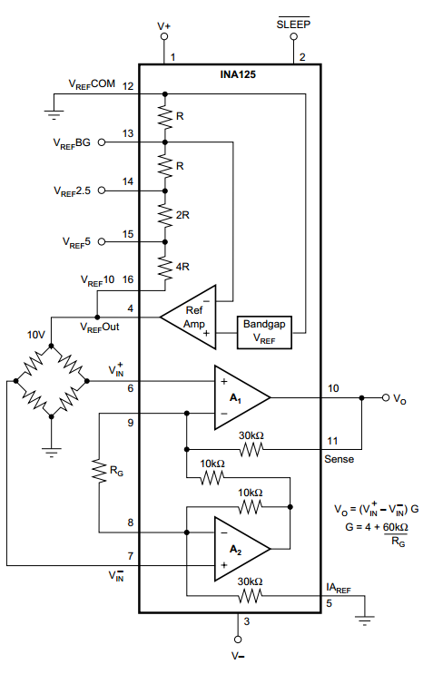
The circuit I'm modeling is a 3-wire, quarter bridge strain gauge, Figure 1, attached to an INA125 instrumentation amplifier, Figure 2.  The three wire circuit shown in Figure 1 minimizes any offset resistance due to resistance in the wires.  The INA125 is used because it has both a clean 10V reference voltage to power the quarter-bridge and a single resistor to control the amplifier's gain.  

Figure 1.  3-wire quarter bridge circuit.  E is the excitation, and e_o is the voltage measurement.  

Figure 2.  INA125 instrumentation amplifier.  Notice the wheatstone bridge on the left side.   

Setting up EAGLE

First, make sure you have the latest version of EAGLE installed.

Next, you need to download some helpful EAGLE libraries.  (The lack of native easy-to-use libraries is one of my biggest criticisms of EAGLE.)  Element14, Adafruit, and Sparkfun all provide additional libraries that are a little simpler to navigate.  Read this link on how to install your libraries.

I also strongly recommend copying all useful libraries to a separate folder so you can find them easier in the future.  For example, I've created a folder called 'JohnsUsefulLibraries', and inside, I have a library for throughhole resistors, throughhole ICs, throughhole trimmers, etc.  To do this, File->New->Library and save it accordingly.  Next, right click on the new library and click open.  Then find the schematic (which should be linked to all of the related parts) in other libraries, right click on it, and click Copy to Library.  Save the new library.

EAGLE Step-by-step procedure to create parts

Schematic

Start with the schematic.
  1. Look through your library and place all parts that you'll need.  
  2. Give each part a Name and Value.  
  3. Move/rotate/mirror/etc each part until you have it where you want it.  
  4. Click "Net" and connect all parts that need to be connected.
  5. Under the supply library, you'll find ground and power symbols.  These are great because they reduce the clutter on your schematic while still being "connected".  Use these and make sure all relevant power or ground symbols have the same name (e.g. all ground symbols should be Named GND) to keep them connected.  
  6. Once done, click "Generate/switch to board"
Figure 3 shows my schematic.  I'm using 3x1 headers as place holders for my standoff connectors (which I couldn't find the part for).    

Figure 3.  EAGLE PCB layout of quarter-bridge strain gauge circuit.  

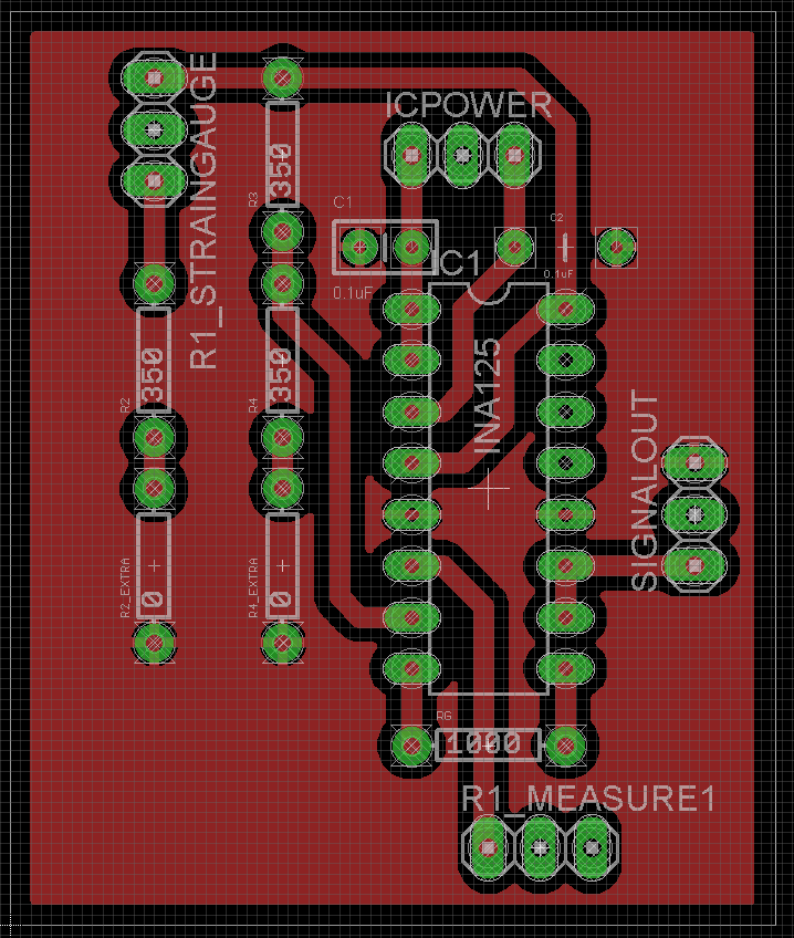
Board

  1. Turn Grid on.  
  2. Move components about where you want them.
  3. Click ratsnet to redraw the "unconnected" lines.
  4. Ground plane
    1. Resize board to something reasonable.  
    2. Change to "Top" layer
    3. Draw polygon around the outside of the board.  Red line should become dotted when connected. 
    4. Change polygon name to GND (name of ground connection).   
    5. Click ratsnet button.
  5. Cleanup silkscreen (optional)
    1. Smash names.
    2. Move and delete desired values.  
  6. Set autorouting values.  
    1. Edit -> Net classes.  
    2. Change traces to maybe 12mil, drill to maybe 20mil, and clearance to maybe 10mil.
  7. Autorouting
    1. Click autorouter.
    2. Continue.
    3. Optionally, place each route manually.  

Figure 4.  EAGLE PCB board layout.  The 0 ohm resistors are there in case I need a second resistor to better balance the bridge circuit.  If I don't need it, I'll just jump it.  


Wrapup

Depending on how you want to have your board developed, there will be additional steps.  I'm presently using a Vinyl cutter and Ferric Chloride to make mine.  For details on this process, see my tutorial on Vinyl Etching PCB Boards.

My final product is shown below.


Resources

INA125 - Instrumentation amplifier
EAGLE tutorials created by Jeremy Blum


Wednesday, November 5, 2014

Pointwise - Converting 2D Plot3d grid files to 2D Plot2d

Introduction
I was trying to use Pointwise to generate Plot2d grids, and I discovered that Pointwise appears to be only capable of generating Plot3d grids.  I couldn't find a solution inside of Pointwise so I wrote the Matlab script below to address it.

A quick explanation on the difference between 2D-Plot3d and 2D-Plot2D grids.  When generating a 2D grid in Pointwise, the program outputs a z-coordinate for each point (which is always 0).  Here's an example of the difference between the 2D-Plot3d and 2D-Plot2d grid file:

2D-Plot3d
2
30 30 1
59 30 1
...xdata(block 1)...
...ydata(block 1)...
...zdata(block 1) = 0...
...xdata(block 2)...
...ydata(block 2)...
...zdata(block 2) = 0...

2D-Plot2d
2
30 30
59 30
...xdata(block 1)...
...ydata(block 1)...
...xdata(block 2)...
...ydata(block 2)...

Why does this matter?  

First, Vulcan doesn't care.  When importing the grid file into vulcanig, the user can specify if it is a Plot3D or Plot2D file, and Vulcan will take care of it.

However, TecPlot DOES care.  Because the output of vulcan is in a true 2D format, TecPlot cannot plot the solution against the 2D-Plot3D grid.  It needs the 2D-Plot2D grid.  


The code

The following code is written in MATLAB

clc; close all; clear all;

%% input
inputFile=['C:\Users\John\Documents\PointwiseExample','\','expansionChamber.x'];
outputFile='grid.x';

%% read in 2D(x=m,y=n,z=1) data
A0 = importdata(inputFile);  %raw data
A=A0;  %raw data to be trucated

% number of blocks in data
numBlocks=A(1);

% grab matrix sizes from the header
for i = 1:numBlocks
    m(i)=A(2+(i-1)*3);
    n(i)=A(3+(i-1)*3);
end

% throw away header info from A
A=A(2+numBlocks*3:end);

% grab x and y data from A and ignore z
for i = 1:numBlocks
    N=m(i)*n(i);
    x{i}=A(1:N);
    A=A(N+1:end);
    y{i}=A(1:N);
    A=A(N+1:end);
    A=A(N+1:end); %delete z
end


%% plot data
figure; hold on
colors=['brkg'];
for i = 1:numBlocks
    plot(x{i},y{i},[colors(i),'+'])
end


%% write 2D(x=m,y=n) data (with the single z value stripped out)
fileID = fopen(outputFile,'w');

% write number of blocks
fprintf(fileID,[num2str(numBlocks) '\r\n']);

% write matrix sizes for each block
for i = 1:numBlocks
    fprintf(fileID,[num2str(m(i)), '\t', num2str(n(i)), '\r\n']);
end

% write x and y data for each block
for i = 1:numBlocks
    p=x{i};
    for k=1:2
        if k==1
            p=x{i};
        else
            p=y{i};
        end
        
        while(length(p)>=4)
    %         fprintf(fileID,[num2str(p(1)), '\t', num2str(p(2)), '\t', num2str(p(3)), '\t',num2str(p(4)), '\r\n']);
            fprintf(fileID,'%1.15e\t%1.15e\t%1.15e\t%1.15e\r\n',p(1),p(2),p(3),p(4));
            p=p(5:end);
        end
        if p~=0
            for j=1:length(p)
                fprintf(fileID,'%1.15e\t', p(j));
            end
            fprintf(fileID,'\r\n');
        end
    
    end
end